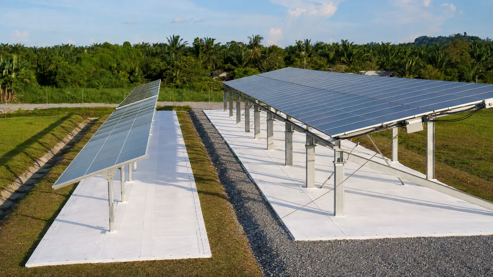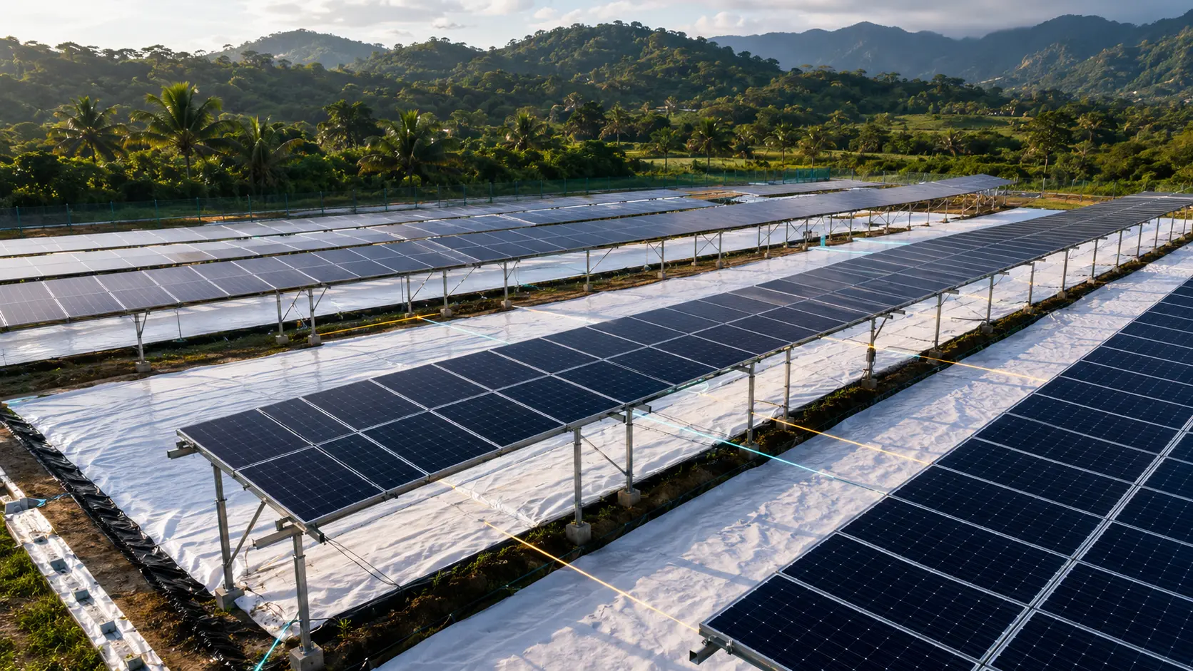
There is no single best height, pitch or membrane width for every bifacial plant. Higher rows and wider pitch can improve rear-side view factor and reduce shading, but they add steel, land, cabling and wind exposure. The optimum is the geometry with the best project economics after energy, structure, drainage, access and membrane cost are modelled together.
Key takeaways
- Do not copy a foreign reference pitch into Malaysia.
- Optimise energy and cost simultaneously.
- Preserve tracker movement, drainage and access.
- Use the actual IFC layout before procurement.
Why height changes rear-side response
Raising the module can expose more reflective ground to the rear side and improve irradiance uniformity. It may also reduce obstruction from vegetation. However, taller posts and frames face greater structural demand, more difficult installation and possibly higher cable or access costs.
Height should be measured consistently—axis height for a tracker, or relevant lower-edge/table reference for fixed tilt. A number without its reference point is not a design input.
Why pitch is a commercial decision
Wider pitch can reduce mutual shading and illuminate more ground, but it lowers land-use density and increases trenching and road lengths. Narrower pitch may fit more DC capacity on the site while reducing the rear-side view of bright ground.
Run energy yield per installed MWp and per hectare. The best pitch for energy percentage alone may not produce the lowest LCOE or strongest equity return.
How much ground should be covered?
Full-pitch coverage is not automatically optimal. The highest-value zones are those that receive light and are visible to the rear of the modules. Coverage hidden in deep shade, used for swales or required for access may add cost without proportional yield.
Map membrane strips around posts, torque tubes, drains, combiner boxes and walkways. For Malaysia, the supplied pre-design workbook indicates 4.6–5.4 m total membrane widths across several common structures, but those quantities are not a national spacing rule.
A practical optimisation sequence
First lock the module, structure family and site constraints. Next run a geometry matrix across plausible height, pitch and coverage values. Screen wind, drainage and access. Finally price each constructable option and compare incremental NPV, payback and LCOE.
The outcome should be a design envelope, not a single unqualified dimension. State tolerances and the assumptions that would trigger redesign.
Frequently asked questions
Questions asset owners and EPCC teams ask
Is 1.5 m the recommended height for every project?+
No. It can be an indicative tracker-axis starting point in a preliminary study, but the correct height comes from the actual structure, energy model, flood level, wind design and access needs.
Does wider membrane always mean more energy?+
Usually the incremental benefit diminishes as coverage expands into lower-value zones. Optimise marginal MWh against marginal installed and O&M cost.
Sources and further reading
External technical and policy links are provided for due diligence. Supplied-reference project claims should be verified against full reports before investment use.
Engineering and investment note: This article is educational content, not a performance guarantee, tender interpretation or investment recommendation. Project results depend on site geometry, measured conditions, equipment, contracts and final engineering.