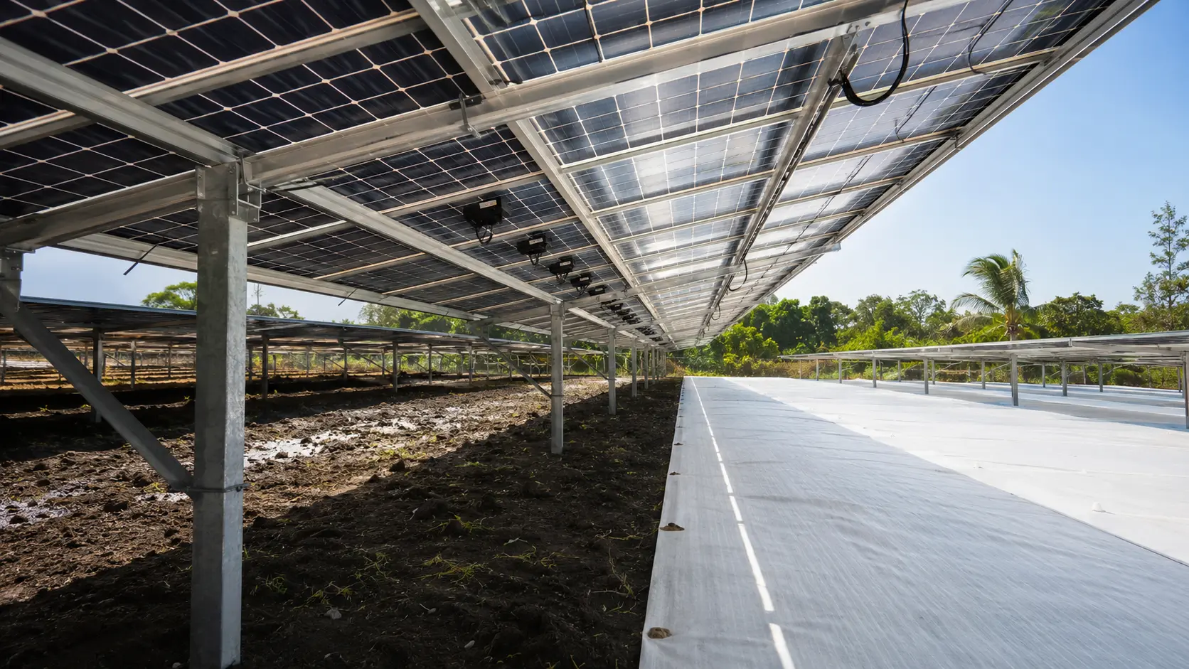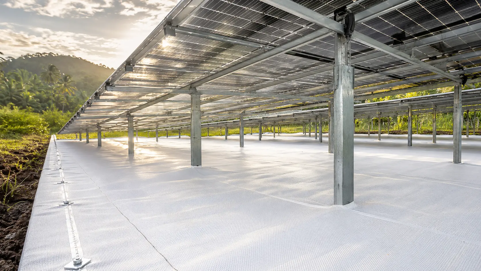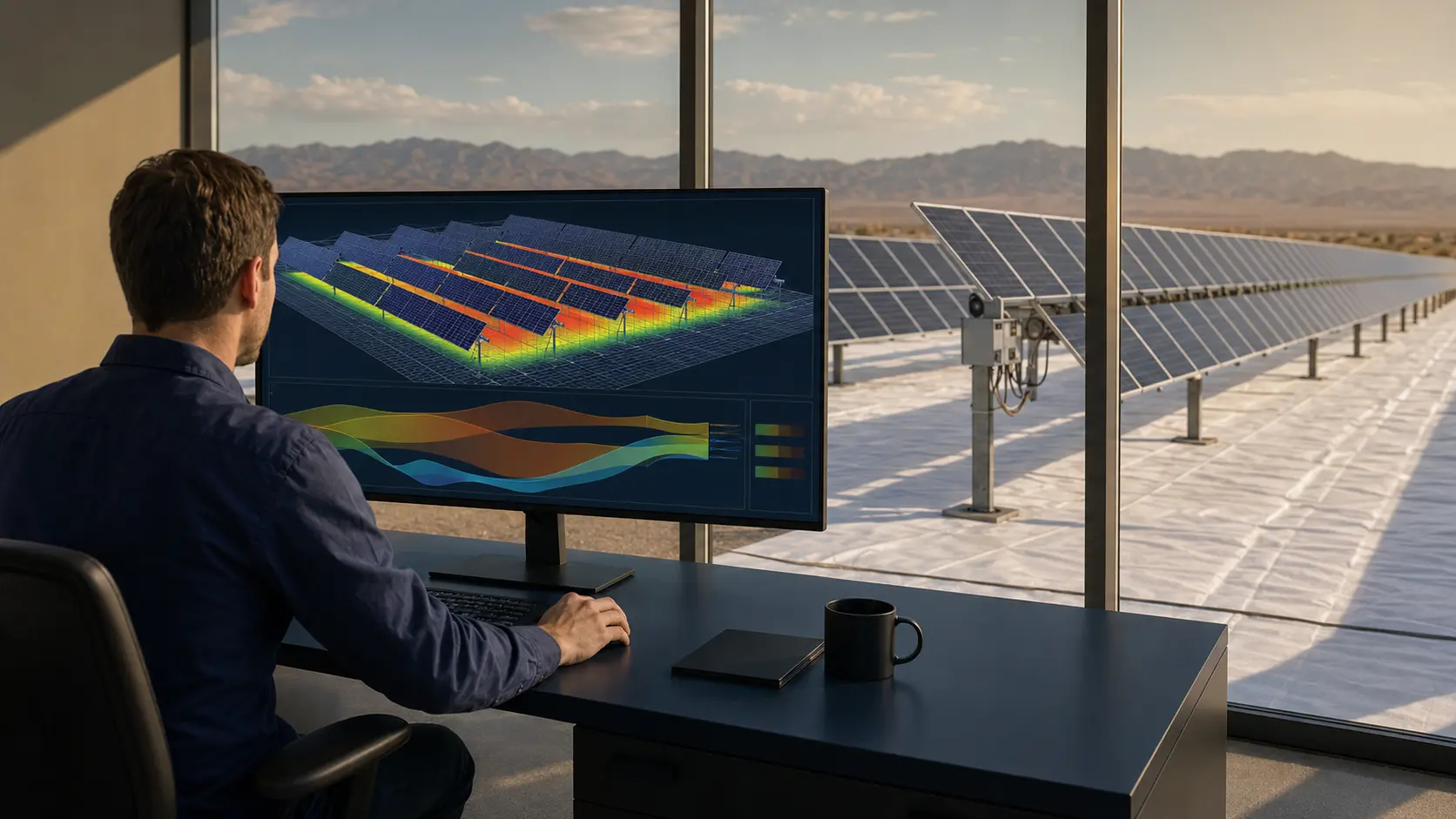
Model a reflective membrane by creating matched bifacial base and intervention cases with the same weather, equipment and losses. Define the real array geometry, structure shading, module bifaciality and ground albedo visible beneath the system. Compare incremental delivered AC energy—not only rear irradiance or DC gain.
Key takeaways
- Use identical base and reflective cases.
- Enter bifacial ground albedo in the bifacial system model.
- Represent actual coverage and geometry.
- Audit the loss diagram and clipping.
1. Lock the baseline
Begin with the accepted project model: the same meteo file, horizon, near shading, module and inverter files, strings, loss assumptions and availability. Calibrate an operating plant against measured data where possible. The reflective case should change only the parameters that the intervention genuinely changes.
Version-control the base and record software version, PAN/OND files and all user-defined parameters. Without a locked baseline, an apparent uplift may come from unrelated edits.
2. Define the bifacial system correctly
Select the bifacial module and enter its bifaciality factor. Use the unlimited-sheds or unlimited-trackers model where the array is sufficiently regular. Confirm pitch, table width, height above ground, axis orientation, module transparency and structure-shading factor.
PVsyst's current two-dimensional approach approximates large regular rows and neglects some edge effects. Irregular blocks, mixed orientations and complex terrain may need additional tools or segmented models.
3. Represent albedo and coverage
Use measured or supported albedo for the natural baseline and the proposed membrane. If only part of the ground is covered, do not apply the clean membrane value to the full pitch without justification. Create an effective albedo carefully or segment the assessment to reflect coverage.
Include a sensitivity for soiling and ageing. Monthly values can represent seasonal changes; a time-series albedo file is stronger where monitored data are available.
4. Interpret results and export evidence
Review global irradiance on the ground, ground reflection loss, rear global irradiance, bifacial gain, mismatch, inverter loss over nominal power and final grid output. Compare monthly and hourly patterns, not only the annual headline.
Document DC uplift, AC uplift and incremental exported energy separately. Attach input snapshots, loss diagrams and a change log so an independent engineer can reproduce the result.
- Baseline and reflective loss diagrams
- Monthly energy comparison
- Hourly clipping comparison
- Coverage and albedo sensitivity
- Reproducible assumption register
Frequently asked questions
Questions asset owners and EPCC teams ask
Should project albedo and bifacial albedo be the same?+
Not necessarily. PVsyst treats far-field project albedo and the ground directly below the bifacial system as separate inputs.
Can PVsyst model partial membrane coverage exactly?+
The standard 2D model uses simplifying assumptions. Partial or irregular coverage may require a carefully justified equivalent value, segmented cases or complementary modelling.
Sources and further reading
External technical and policy links are provided for due diligence. Supplied-reference project claims should be verified against full reports before investment use.
Engineering and investment note: This article is educational content, not a performance guarantee, tender interpretation or investment recommendation. Project results depend on site geometry, measured conditions, equipment, contracts and final engineering.